

CapeHorn
Self-steering gears
“After fifty years of sailboat cruising without steering my boat, I’ve mastered the art of staying on course.”
— Yves Gélinas
Inventor of the CapeHorn self-steering gear
While coastal sailing or racing, it is pleasant to steer by hand. On a long-distance cruise or an ocean passage, we have better things to do.
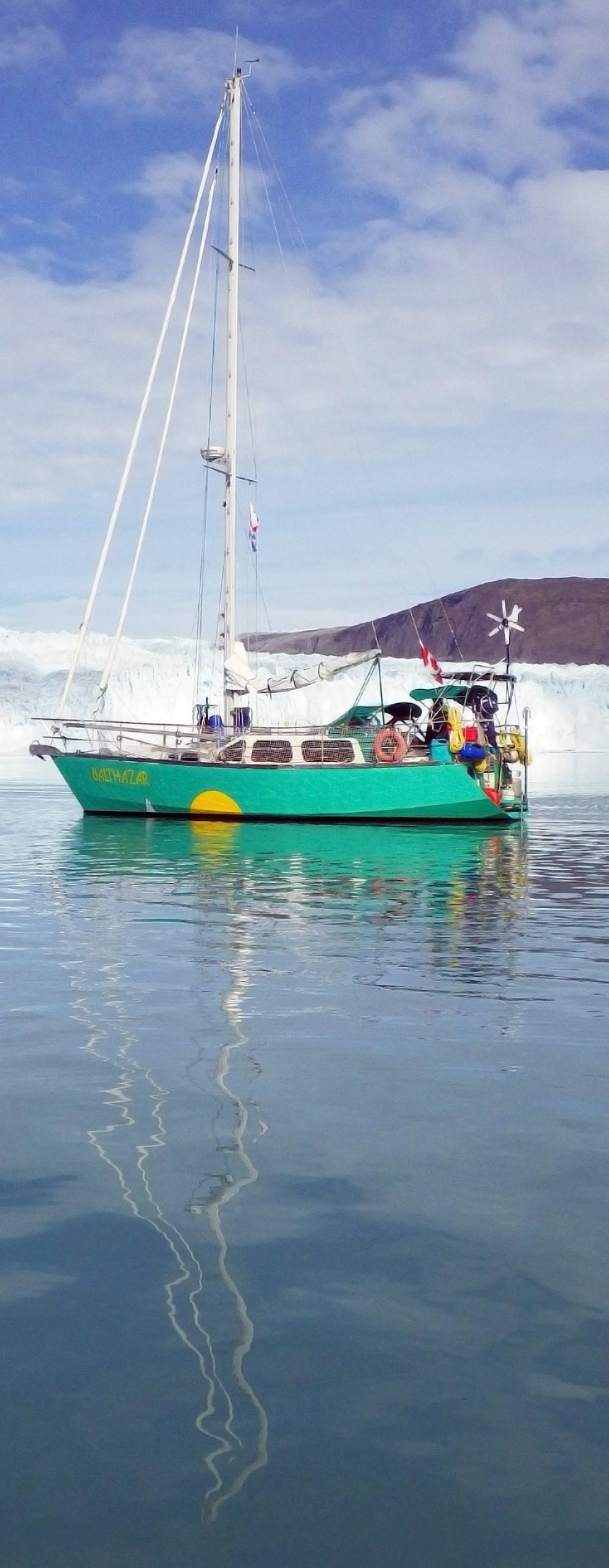
Avoid being stuck at the helm with a CapeHorn self-steering gear. CapeHorn maintains a constant angle to the wind and offers stable and safe sailing, regardless of the strength of the wind or the state of the sea. Bonus, it does not need electricity and never gets tired!
Performance of the CapeHorn
The CapeHorn self-steering gear is the result of ten years of research. Before it was offered to sailors, its resistance and performance were tested in a solo circumnavigation via the Roaring Forties and Cape Horn (hence its name).
There are presently two ways to mechanically keep a boat on course: through an auxiliary rudder or using the rudder of boat. CapeHorn uses the rudder of the boat, which is more efficient in shape and surface than an auxiliary rudder, especially in rough seas.
7 good reasons to choose a CapeHorn
1. Custom-built for a perfect fit on the boat it steers
2. Maintains course even downwind in light air
3. Environmentally friendly, it only uses water and wind energy
4. Made of stainless steel and high-quality polymers
5. Designed, tested and manufactured by experienced sailors
6. Elegant and discreet, it does not prevent the use of davits, stern arch of solar panels
7. Uses the rudder of the boat, more efficient than an auxiliary rudder
How does the CapeHorn self-steering gear keep course?
To set the course, the turret is rotated so that the wind hits the vane on its edge; as soon as the boat wanders off course, the pressure of the wind on one of its faces the vane tilts the vane.
The tilt of the vane rotates a paddle in the water behind of the boat; as soon as it rotates, the water flow drives this paddle laterally with force. This force is transmitted to the steering gear through control lines that pull the rudder to bring the boat back on course.


")


CapeHorn, a self-steering gear perfectly adapted to your boat
How to cross an ocean without getting tired
“Delegate the task of steering to the best possible crewman, a CapeHorn self-steering gear. The only crew member who only consumes wind and water. Plus, it looks good!”
– Guy Lavoie, sailor and production manager.
Quotes from CapeHorn Users
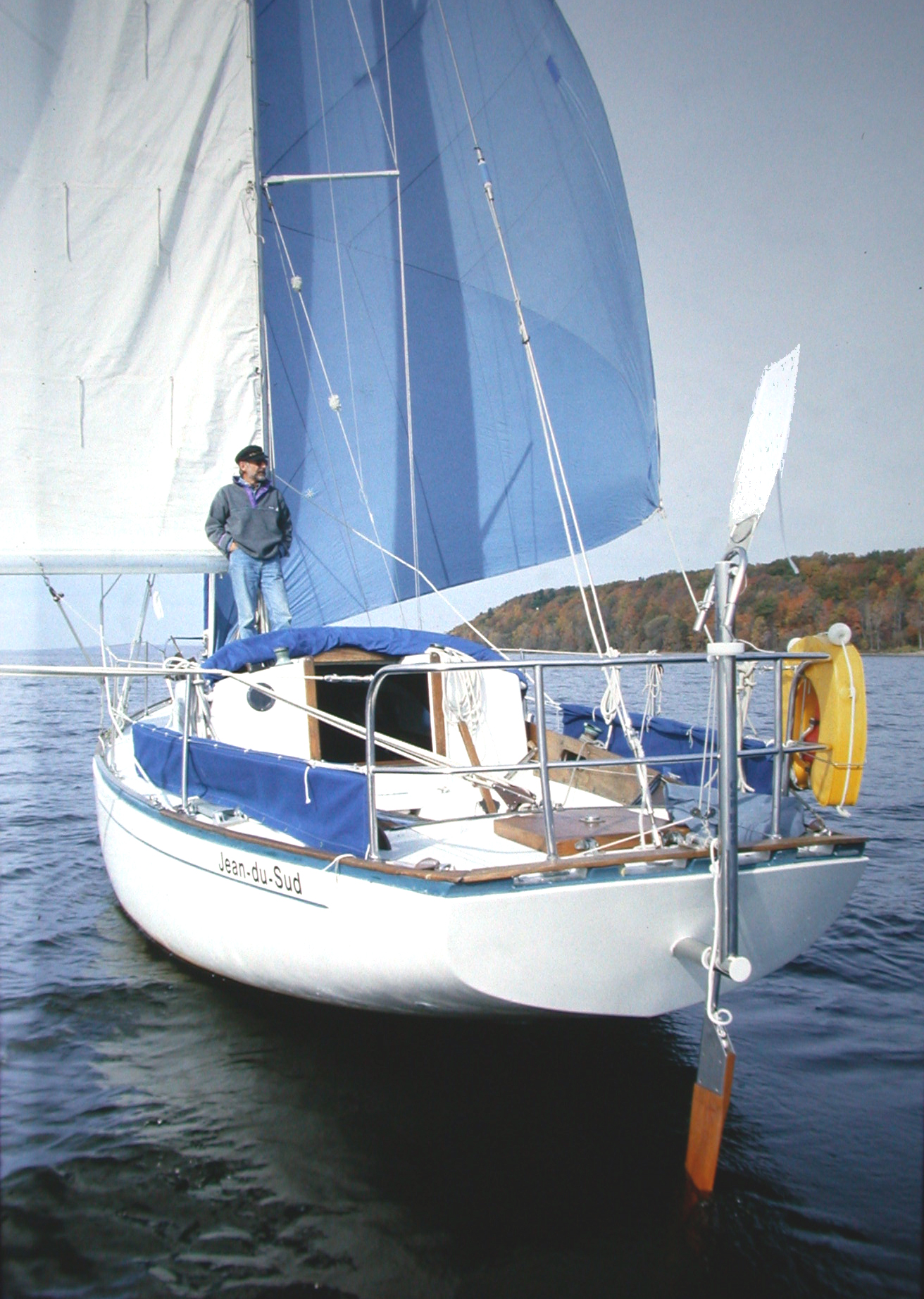
Excerpts from the (multiple award-winning) film With Jean-du-Sud Around the World Shot by Yves Gélinas, designer of the CapeHorn, while he was testing the prototype around the world, through the Roaring Forties.
Christian Williams has written five books on sailing. The YouTube channel, ChristianWilliamsYachting, has more than 10 million views. At over 70, he has made three solo round trips to Hawaii.
Dan and Kika met during their architectural studies in the United States. In 2014, they bought and refurbished an old Pearson 36, naming it Uma, and set out to explore the world, from the Icy Arctic to the tropical Caribbean.
Ocean Cruising Club member John Stone sails Far Reach, a Cape Dory 36 that he completely refitted over the course of six years. Videos of the refit and his cruises can be found on the FarReachVoyages YouTube channel.
In the heart of the endless ocean, where wind and waves dance in harmony, the albatross reigns supreme in the skies. Majestic and graceful, it embodies freedom and mastery of the elements.
Just as the albatross is the guide of sailors through oceans, the CapeHorn represents your faithful travel companion, ready to accompany you with reliability, elegance and precision.
The wisdom of the albatross, which has sailed the seas for centuries, is reflected in the design of the CapeHorn. Robust, reliable and adaptable, our product embodies the seafaring spirit, ready to face the challenges the ocean presents.
Together, the Albatross and the CapeHorn form a perfect symbiosis, an alliance between nature and technology, offering sailors an unequal sailing experience.
Frequently Asked Questions
Self-steering gear or electric autopilot?
There are two ways to make a boat steer itself: electric pilot, or self-steering gear.
In long distance cruising or passage making, it is best to use a self-steering gear that does not consume electricity and never gets tired. Regardless of the strength of the wind or the state of the sea, it maintains a constant angle to the wind.
The stronger the seas, the more an electric pilot consumes and the more likely it is to let you down.
A CapeHorn gear combines these two modes of steering, wind and electric: when the wind is absent or irregular, the vane can be replaced by a tiller pilot that controls the paddle of the self-steering gear, which still provides the power to move the rudder. Thus, the smallest pilot will steer even a large boat effortlessly, at the cost of a few milliamperes.
Auxiliary rudder or rudder of the boat?
There are two ways for a self-steering gear to maintain a constant point of sail:
– An auxiliary rudder controlled by a wind vane, the rudder of the boat being blocked.
– Or using the rudder of the boat.
However, a vane alone being too weak to act directly on a rudder its impulse is amplified with the help of a paddle planted in the water behind the boat. Rotating vertically under the impulse of the vane, it is forcefully driven sideways by the water flow, providing the energy to pull the rudder.
CapeHorn uses the rudder of the boat for three reasons:
Better performance, especially in heavy weather, the rudder of the boat being more efficient and bringing the boat back on course more quickly.
Better performance in light air, especially downwind: it takes less wind to rotate a narrow paddle than an auxiliary rudder.
Drag of a paddle is negligible; drag of an auxiliary rudder is appreciable.
How does a CapeHorn self-steering gear keep course?
To set the course, the turret is rotated so that the wind hits the vane on its edge; As soon as the boat wanders off course, the pressure of the wind on one of its faces tilts the vane. As it tilts, it rotates a paddle planted in the water at the back of the boat, which is pushed sideways with force by the water flow. This force is transmitted to the steering gear through control lines that pull the rudder to bring the boat back on course.

How strong a wind is needed for a CapeHorn to work?
As soon as there is enough wind to carry sail, CapeHorn will steer, even downwind. And as long as canvas can be carried, even beyond.
Is CapeHorn useful in racing?
Racers generally prefer to rely on an electric pilot that maintains a compass heading. But a self-steering gear maintains a constant angle to the wind and reacts to wind oscillations, so the sails always work at their maximum efficiency.
Two examples:
Summer of 1983. A few months after returning from its round-the-world voyage, with a reduced crew and steered by the Cape Horn prototype 90% of the time, the Alberg 30 Jean-du-Sud won the third leg of the Gulf Cup (Îles-de-la-Madeleine – Gaspé, 150 miles) against more recent boats with racing sails and helmed by seasoned crews.
In preparation for the Governor’s Cup (1750 miles between Capetown and Saint Helena in the Atlantic), Ian Williams, racing solo against crewed yachts, equipped his boat with a CapeHorn to double his electric pilot. After a day at sea, the engine broke down and could no longer recharge the batteries. Ian Williams completed the race with his CapeHorn and finished second in class.

Photo Ian Williams
How to adapt a Cape Horn to a given boat?
Several ways:
Click on “Documentation”, then “Boats steered by CapHorn” to access the list of boats we have already equipped, the model needed and its dimensions for a perfect fit.
In “Documentation”, consult the PDF “How to measure” which indicates the measures needed to adapt a CapeHorn to a given boat.
Click on “Request a quote” and send us photos illustrating the stern of your boat, the inside of the lazarette and steering gear belowdecks. If there is a bimini, an arch, davits, solar panels, etc, include photos. We will recommend the most elegant way to make your boat steer itself and guide you in the measuring.
Is CapeHorn compatible with hydraulic steering?
We know that wheel center on a hydraulic steering is not constant due to leakage of fluid inside the circuit; this is why leading the lines to a drum on the wheel in the conventional manner does not work. But as the Jean-du-Sud and Spray models are integrated into the boat, the lines can be led internally through blocks fastened to a short tiller (which can be the same as the one used by the hydraulic system), then to jamming cleats in the cockpit for instant connect, disconnect or trim. However, a bypass valve is needed when CapeHorn is at the helm.
Can CapeHorn be used with davits, an arch, a bimini?
The integrated Jean-du-Sud and Spray models use only 4 inches of space behind the boat. A dinghy under davits is only this much farther aft.
On the Varuna and Joshua outboard models used on a scoop stern, the windvane tower is at the front end of the horizontal axle, against the transom and a dinghy can be hoisted above the scoop.
The vane can be located below or above an arch or solar panels, depending on their height.
What is the price of a CapeHorn?
The final price varies depending on the model and its dimensions. Click on “Request a quote”.
What is included?
All the hardware needed to fasten the gear on the boat is included; however, blocks and hardware needed to lead control lines to the steering gear are not, being different in number and type for each boat. They are acquired locally.
What is the guarantee?
Marine quality! We are sailors: before each CapeHorn self-steering gear is shipped, we make sure it is free from manufacturing defects and we could use it ourselves around the world. It is guaranteed against damage caused by sea or wind for a period of 3 years after delivery.
Are spare parts needed?
A CapeHorn self-steering gear is strong enough and wear-resistant in the first place and does not need spare parts. However, in the event of loss overboard, some owners prefer to double detachable parts such as vanes, crescent that connects them to the turret, or paddle.
The only part that needs to be replaced is the bungee cord that connects the blade to its stock and allows it to break away in the event of an impact; it needs to be replaced after a season or two, as it stretches over time.